Promising new opportunities for quantum research are being opened through the study of acoustic waves on solid surfaces or in bulk. In this research area, investigations commonly rely on complex analog arrangements with tunable attenuators, power splitters, and phase shifters to attain the desired frequency coverage and signal stability over various channels.
The Zurich Instruments SHFSG+ Signal Generator is equipped with intuitive graphical software to simplify measurement processes and, in turn, provides all these features out of the box.
Acoustic waves produce electric, dynamic, and nanoscale strain fields as they permeate through piezoelectric materials, providing a contactless, adaptable approach to controlling quantum states in quantum dots, low-dimensional semiconductor systems, and additional solid-state platforms.1,2
Acoustic waves enable critical features such as coupling and control of quantum bits for quantum sensing applications because they can be engineered to interact coherently with spins, charge carriers, or optoelectronic excitations.
The Paul Drude Institute for Solid State Electronics has a core specialty in managing acoustic fields in electronic devices. At the research institute, two experiments were performed utilizing the SHFSG+ Signal Generator, demonstrating how acoustic excitations can be used as a versatile instrument.
In contrast to the traditional use of tunable attenuators, power splitters, and phase shifters, the SHFSG+ makes the studies it supports more accessible by offering multiple synchronized channels and accurate digital control of the amplitude and phase of microwave signals.
In the first section of the article, a study is outlined that aimed to produce complex surface patterns using overlapping surface acoustic waves (SAWs). In the latter section, the coupling between optical photons and microwaves is explored, with the acoustic fields mediating the coupling.
Both experiments were carried out on two successive days within 24 hours, made possible by the similar aims and extensive expertise shared by Zurich Instruments and PDI Berlin researchers.
Generation of Complex Surface Patterns
In the specialism of quantum control, accurate and coherent management of SAWs is fundamental for their use. In the first study, the capability of overlapping and controlling SAWs with the SHFSG+ Signal Generator is demonstrated.
Complicated dynamic strain patterns on the surfaces of solid-state devices can be revealed by spatial overlap of SAWs.
An acoustic vortex, an innovative dynamical phenomenon that can be used to modulate light reflected on the device’s surface, can be produced with accurately controlled phase differences amongst three interfering standing SAWs. Acoustic vortices are swirling motion patterns where the material’s elements rotate across a central axis.
Experimental Setup
The device under test (DUT) consists of a sapphire substrate with a sputtered ZnO layer. Planar interdigitated transducers (IDTs) are formed on the surface of ZnO. The six IDTs are positioned in a circle, thereby forming three SAW cavities rotated by 120° in relation to one another (as shown in Figure 1a).
Complicated interference patterns can be produced through the excitation of IDT pairs with particular phase differences. The study is performed at room temperature.
The SHFSG+ Signal Generator’s wave outputs are used to connect the IDTs. The application of microwave signals to the IDTs excites the SAWs. Supplying continuous-wave (CW) microwave signals at the resonant frequency of the device, f0 = 610.5 MHz, targets the fundamental vibrational mode, producing standing-wave patterns.
Scanning laser interferometry is used to electrically measure the standing-wave patterns, enabling mapping of the local SAW field’s amplitude with sub-micrometer resolution.3 The reflected laser beam is translated into electrical signals and quantified.
The microwave channels’ output range is configured to 5 dBm, before being amplified with room-temperature amplifiers providing a nominal gain of 16 dB.
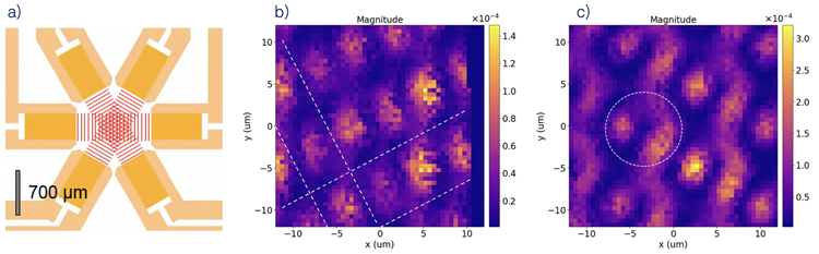
Figure 1. (a) Layout of the device under test with three pairs of IDTs in a circular arrangement. Acoustic standing waves are generated in the white interior area when applying microwave signals at f0 = 610.5 MHz. (b) The spatial map of the measured amplitude. Two pairs of IDTs are excited in phase. White dashed lines indicate the positions of acoustic nodes. (c) The spatial map of the measured amplitude. Three pairs of IDTs are excited with 120° of phase difference between every two pairs. This creates an array of vortices on the sample surface. A white dashed circle is added as a reference to indicate the formed vortex. Image Credit: Zurich Instruments AG
Results
A simple pattern is generated by applying in-phase CW signals to two IDT pairs. The measured amplitude in a specific area is displayed by the color plot in Figure 1b.
The map’s brightest regions are areas of maximum amplitude and relate to the maximum surface displacement of the standing waves (anti-nodes). Along with the nodes, the anti-nodes occur at regular intervals across the entire scanned area.
Acoustic waves are produced in two directions, leading to nodes and anti-nodes that form a diamond-shaped arrangement. In Figure 1b, the node positions are signified with white dashed lines.
When CW signals are applied to all three IDT pairs, a more advanced arrangement is formed. Between the two pairs, the microwave phase difference is set to 120°, yielding 0° for IDT pair one, 120° for IDT pair two, and 240° for IDT pair three.
The measured amplitude under these conditions is presented in Figure 1c. The patterns are periodic again but obviously vary from those in Figure 1b. When observing the bright regions, they are extended and adopt ‘shrimp-like’ shapes. To highlight one of the ‘shrimp-like’ shapes, a white dashed circle is included in the plot.
The presence of this type of feature is consistent with the circulating motions of the surface material elements. The minimum surface displacement at the core corresponds to the center of the vortex.
The precise time evolution of the swirling surface element can be determined by capturing both the phase and amplitude. Additional careful calibration of the phase difference and microwave amplitude can enhance the shape of any vortex.
Acknowledgments
Produced from materials originally authored by Luk Yi Cheung from Zurich Instruments.
References and Further Reading
- Maity, S., et al. (2020) Coherent Acoustic Control of a Single Silicon Vacancy Spin in Diamond. Nature Communications, 11, 193. DOI:10.1038/s41467-019-13822-x. https://www.nature.com/articles/s41467-019-13822-x.
- Kuznetsov, A.S., et al. (2023) Microcavity Phonoritons – a Coherent Optical-to-Microwave Interface. Nature Communications, 14, 5470. DOI:10.1038/s41467-023-40894-7. https://www.nature.com/articles/s41467-023-40894-7.
- Liou, Y.-T., et al. (2024) Spatial Analysis of Multi-Frequency SAW Beams Excited by Slanted IDTs on ZnO-SiC Heterostructures. Journal of Physics D: Applied Physics, 57, 415302. DOI:10.1088/1361-6463/ad600e. https://iopscience.iop.org/article/10.1088/1361-6463/ad600e.

This information has been sourced, reviewed, and adapted from materials provided by Zurich Instruments AG.
For more information on this source, please visit Zurich Instruments AG.